Development of Mach Scale Swashplateless Rotor with Integrated Flaps for Primary Control
[Jayant Sirohi, Keith Allen, Peter Copp]
Primary flight control in helicopters is currently accomplished through a mechanical swashplate. The swashplate assembly is heavy, complex and maintenance intensive. In addition, the exposed linkages result in a large drag penalty during forward flight. The high performance penalty and probability of failure of swashplate systems has recently motivated research in to development of a swashplateless rotor utilizing an alternative control method. The objective of the present work is to experimentally evaluate the feasibility of on-blade trailing edge flaps as a primary control device through the testing of a Mach-scaled rotor model.
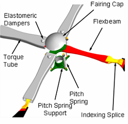
Figure 1: Conceptual drawing
of a swashplateless rotor
Numerical simulations have indicated that trailing edge flaps can satisfy the requirements for primary control. In addition, trailing-edge flaps actuated by piezoceramic benders have been successfully employed for vibration control of Mach-scaled and Froude-scaled rotors However, primary control requires the use of larger flaps, more powerful actuators, and lower blade torsional frequency as compared to vibration control. Implementation of these characteristics within the volumetric constraints of the rotor blade, while maintaining low weight and sufficient structural integrity, poses a major challenge in the development of the swashplateless rotor.
The primary source of control is a change in blade pitch angle created by deflecting the trailing-edge flaps. This is accomplished by reducing the torsional frequency of the blades, so that the pitching moment created by the deflected trailing-edge flaps results in a twist of the blade. An upward flap deflection creates a moment that raises blade pitch and increases lift force, whereas a downward deflection has the opposite effect. Steady up or down flap deflections produce collective pitch control, and properly phased sinusoidal flapping at the rotational frequency provides cyclic control. However, reducing the torsional frequency without compromising structural integrity, especially in a model scale rotor blade, is challenging. Therefore, the present approach relies on a spring loaded pitch link in conjunction with a torsionally rigid blade to achieve the required torsional frequency. By varying the stiffness of the linear springs in the pitch link, the effective stiffness of the pitch link, and hence the torsional frequency of the blade can be changed. Additionally, studies have found that a proper blade index angle (pre-collective pitch) can reduce aerodynamic penalties and flap power requirements.
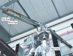
Figure 2: Rotor mounted on instrumented hover stand.
The present work focuses on a 2-blade, 66-inch diameter composite rotor with a NACA0012 profile, and embedded trailing edge flaps. A foam core wrapped in graphite-epoxy 0/90 cloth gives the blade shape and torsional stiffness, while a unidirectional graphite-epoxy spar provides axial strength and attachment points for the hub and flap mechanism. Tension tests of the spar confirmed the structural integrity of the rotor up to the design speed of 2300rpm. Optimum flap size and location were determined in a previous study using University of Maryland Advanced Rotorcraft Code6 (UMARC). Following this analysis, a flap of size 28% radius length and 15% chord width centered at 75% radius was chosen to minimize actuator power requirements and control authority.
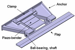
Figure 2: Rotor mounted on instrumented hover stand.
Multi-layer piezoceramic benders were chosen to actuate the flap due to their compactness and energy efficiency. A set of anchor plates fixed to the spar cantilever the bender, which is mated to the trailing edge flap with a pin-cusp device. Figure 3 shows a drawing of the assembled flap mechanism. A finite element model of the bender was created using an Euler-Bernoulli beam model with induced strain actuation. The model was then validated and used to investigate the effects of length, taper pattern, number of layers, rotational speed, and hinge-offset on bender performance. From these results, an optimal bender design was chosen to meet the required hinge-moment and deflection angle of the control surface, while remaining within the size and weight constraints of the blade.