Flapping-Wing-Based MAV:Insect-Based Mechanicm
[Beerinder Singh, Mat Tarascio]
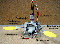
Fig. 1: Flapping Wing Mechanism
Flapping wing biomimetics-based micro aerial vehicles may offer the possibility to realize efficiently aerodynamic lift in low Reynolds number environment. Additionally, a flapping wing system may provide the potential to be less sensitive to gusty environment, which is key factor for a stable flight of a micro air vehicle in confined environments. The objective is to conduct experimental and analytical research activities to design and develop hover-capable, flapping wing micro aerial vehicles. We have developed the flapping-wing test bed, which operated flapping wings with prescribed motion in air at high frequencies, with a typical Reynolds number of 15,000. Also, lightweight and flexible wings were used to attain high frequencies. This flapping system is a passive-pitch, bi-stable mechanism, capable of emulating insect wing kinematics.
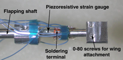
Fig. 2: Miniature bending beam load cell
A miniature bending beam load-cell was designed and built to measure the thrust generated by the flapping wings. Wing mass has a significant effect on the maximum frequency that can be achieved with such a mechanism. Light wings were constructed with an aluminum or composite frame covered with a Mylar sheet. However, lighter wings turned out to be more flexible, leading to greater aeroelastic effects. For all the wings tested, the thrust dropped at high frequencies, thus indicating the need to incorporate wing deformations into the analytical model.
Based on the observations from the experiments, an aeroelastic model was developed and refined. The wing was modeled as a thin plate undergoing a large overall flapping/pitching motion. Plate finite elements were used to calculate natural frequencies of wings, and then the modal reduction was used to obtain aeroelastic response. An aerodynamic model based on indicial unsteady aerodynamics was implemented, which included the effect of wing deformations. A blade element based aerodynamic analysis was formulated consisting of following components:
- translational and rotational circulation based on thin airfoil theory
- leading edge vortex modeling using Polhamus’ leading edge suction analogy of delta wings at high angles of attack
- non-circulatory forces based on thin airfoil theory
- effect of the starting vortex on the translational and rotational circulation using Wagner function
- effect of the shed wake and a tip vortex using Kussner function, and
- induced inflow velocity distribution based on momentum analysis.
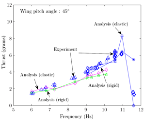
Fig. 3: Comparison of measured and predicted thrust
Detailed flow measurements on a flapping wing were carried out using a laser sheet at mid-span. Results show a series of images acquired at different positions in the flapping cycle starting from (b) the mid-point of supination to (i) end of pronation. A number of vortical structures occurred near the trailing edge. Not only a large starting vortex was observed, but also multiple leading edge vortices were noticed. Next, the aeroelastic model was used to predict the thrust measured on the flapping wing test bed, for different wing designs and different pitch angles. Results were obtained for both an uncoupled as well as coupled analysis. In the uncoupled analysis, the wing structural deformations were computed under inertial loading alone. These deformations were then passed on to the aerodynamic analysis to obtain the airloads. In the coupled scheme, the airloads were fed back to the structural analysis to re-compute the system response and iterated until convergence was achieved. Figure 3 shows the average thrust predictions using the rigid and elastic analysis compared with the experimental results. The rigid wing analysis was unable to pick up the drop in thrust at high frequency. However, the elastic analysis captured this effect. This underscores the importance of including aeroelastic effects in modeling flapping wing flight.