Flapping Rotor System
[Brandon Fitchett]
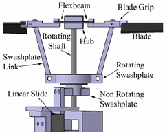
Figure 1: Flapping Rotor Swashplate and Hub
Some of the negative effects of low Reynolds numbers include a reduced lift to drag ratio as well as a reduced maximum lift coefficient when compared to full-scale helicopter counterparts. The objective is to show that unsteady aerodynamic properties, especially dynamic stall can be used to increase the thrust capabilities of small MAV rotors. In order to achieve the desired motion, we have designed a special mechanism that is capable of independently flapping and rotating its blades. The rotor could operate in two unique configurations or in a combination of both configurations.
In the first configuration, the blades were flapped with the flapping motor and the hub rotated freely due to the inclined vectors of the aerodynamic forces on the blades. This was called as pure flapping (with passive rotation). Thrust could be achieved with pure flapping/passive rotation, but was found less efficient at producing thrust than a conventional rotor.
The second configuration was the pure rotation mode where the rotor utilized conventional rotation with a motor driving the shaft. When both modes were combined, the rotor could flap and rotate independently at different speeds. There were a few new variables, which must be finely balanced in order to show benefits from this type of motion.
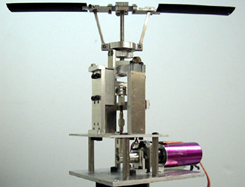
Figure 2: Experimental Apparatus
The flapping amplitude and flapping frequency were mechanically limited by reciprocating forces. The flapping motion was defined in terms rotor revolutions. The flapping frequency must be high enough in order to harness the benefits of dynamic stall and other unsteady aerodynamic phenomena. The blades were flapped at 2/rev, 4/rev and 6/rev at 660 and 1000 RPM. The respective reduced frequencies were 0.15, 0.3 and 0.45. The flapping amplitude must be high enough for the blades to reach beyond their statically stalled angle of attack in order to produce extra lift, but the amplitude should not be so high that the blades fall below a useful minimum angle of attack during their harmonic flapping cycle. The blade flapping amplitude was chosen carefully for each flapping frequency to cause a nearly constant angle of incidence variation across the radius of the blade. The blades were made of 2.0 cm x 6.2 cm aluminum rectangles that were pressed and formed over a cylinder to give them a camber of 7%. Their leading edge was then sharpened at an angle of 15° down with respect to the upper surface. These blades were proven very efficient in earlier tests. At 4/rev blade flapping (k=0.3), the maximum thrust coefficient improved by 6% while operating at maximum figure of merit and the torque reduced by 10%.